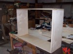
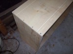
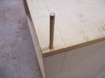
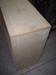
Memories of Triumph


Production at Triumph seems to have been pretty variable, with different ideas and directions being tried out. Roger White and David Earp worked on ac50s and ac100s in the mid-60s.  Then, when work got slack, they were ‘lent out’ to Brooklands, the nearby company that made the faceplates (and later on circuit boards for solid-state models). As well as 7/4 series panels, Brooklands made panels for the vox domino & ac4. Edward Rook (Brooklands) had gone into screen printing; panels were sprayed, then fed by conveyor through a baking unit.

rwchassis ( Initials on ac50 chassis, Roger White, & probably his friend David Earp, click to enlarge )

Before moving to Brooklands, Roger and David worked on amps like the ac50 for supplying to Vox. Roger  was there roughly from 1963-66; he remembers his first pay-slip as being for “.. 3 pounds, 17 shillings  and sixpence, as it wasn’t a full week.  I’d go through boxes of el34s, matching good push-pull pairs…I’d test them, making sure they got to 50 watts, the valves just glowing cherry red, before the sine wave started to flatten off on the scope. We used to stand the little ones up on their sides; they’d store a charge though,  and we soon learnt not to pick them up by the transformer after some nasty shocks.

I remember the reverb units; ceramic cartridges with a bit of bent wire, coiled & soldered to the head of a brass OBA or 2BA bolt. There was total feedback on the first one, until they realised they needed to wind it in one direction towards the OBA/2BA, then in the opposite direction to the other end.

(more…)

Posted in blog

welcome Vox 4series 7series

welcomeblack


“When we finished ”Revolver”, we realised that we had found a new British sound almost by accident.”

  – Paul McCartney, 1966

sitemainicgrab

newtitles

The life & times of the rare Vox 7 & 4 – series amplifiers, 1966-68.

(**Blog Index, & Gallery links now all active).   Further entries added as website unfolds.  Either scroll down ↓  to see just the most recent posts on history / amps / memories (click on  ‘more..‘  to expand full post),  or see blog post INDEX above for the whole list & links to individual posts.


Posted in blog | Tagged , , , , , , |

New builds of 4120 and 7120 cabs – Part I

5-17-14-19

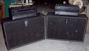
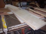
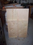
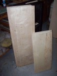
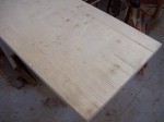
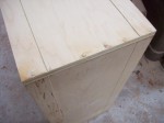
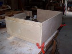
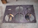
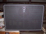
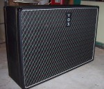
These reproduction cabinets are made from 9 ply, cabinet grade 3/4” plywood. The measurements for each cab is 42” X 29” X 13”. The measurements were taken from an original 4120 cabinet that resides in the UK (Thanks Mike Handley!!). The back panels are made from 3/8” thick Baltic Birch, as this is a much better grade of wood that you’d find at a building materials store and it is a true 3/8” thick. The building supply 3/8” plywood isn’t a true 3/8” thickness and is way too flimsy for back panel usage.

MEASUREMENTS:
Cabinet Material: ¾” Cabinet grade plywood, 7 to 9 ply.
Rear panel material: 3/8” Baltic Birch.
Gold Cabinet Piping: 2 1/8” inside from each edge.
Piping Channel depth: 3/32”.
Piping Channel width: 1/8”.
Hand Wheel trolley mounting holes: 12 ¼” down from top of side.
Rear input jack (4120 cab): 6 ¾” down from top center.
Rear input jack (7120): center of top rear panel.
Front Baffle mounting strips depth, in from front edge: 1 ¼”.
Rear Panel mounting strips depth, in from edge: 3/8 to 7/16”.
Midax Horn baffle location: Down from top – 6” / In from the side – 4 ½”.
Midax Horn cutouts: 2 ½” X 5 5/8”.
12” Speaker baffle holes: 11” circle.

You will need approx 4 yards of Tolex; cabinet is approx 12’ around (tolex is usually cut from 54” high rolls).
You will need 17 yards of .080” Gold Piping = approx 51’.
8 yards of White baffle piping.
3 yards of VOX grillcloth.

Cabinets are 42” X 29” X 13” .
4120 Rear Panel: approx 40 5/16” X 27 5/16”.
16 Speaker mounting baffle machine screws & nuts: 1 1/4” to 1 ½” long.
20 2 /1/4” X 10/32 Midax Horn mounting machine screws & nuts.

CLICK ON THE THUMBS FOR LARGER IMAGES

  • 4-11-14-1
  • 4-11-14-2
  • 4-14-14-3
  • 4-25-14-2
  • 4-25-14-1
  • 4-25-14-3
  • 4-25-14-4
  • 4-28-14-2

I went ahead and drilled the side panels for the trolley mounts just in case an original or a re-issue 7120 trolley should ever become available. Not likely, but the holes are there under the tolex just in case.

The other tolexed cabinet in this 1st set of pics is a ‘Supreme’ donor cabinet that I had in my collection. I used this for the inside cabinet measurements and for the original baffle hardware which I used on the 7120 build. The 4120 build used all new mounting hardware.

  • 4-29-14-5
  • 4-29-14-1
  • 4-29-14-2
  • 4-29-14-3
  • 4-29-14-10
  • 4-29-14-4
  • 4-29-14-7

(more…)

Posted in blog

New Builds of 4120 and 7120 Cabs – Part 2

  • 5-9-14-1
  • 5-9-14-3
  • 5-9-14-4
  • 5-9-14-6
  • 5-10-14-1
  • 5-10-14-2
  • 5-10-14-5
  • 5-10-14-7

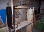
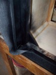
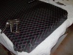
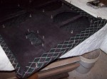
I applied the tolex all the way around the cabinet and allowed for the seam to be at the bottom center. I started at the bottom and made my way around the entire cabinet, gluing the center section down with titebond and smoothing it out with a ‘J’ roller. Allow for several inches on each side to allow for tucking and trimming when doing the final gluing / fitting. Rather than splitting the tolex down the center of the gold piping channel, I elected to use hard maple strips to press the tolex and the gold piping into the piping channels. The ‘splitting’ technique works well, but I found that using this alternate method worked just fine. Then I used contact cement to glue down the outside sections of tolex to the cab. Before I started gluing the tolex, I used black spray paint to spray the piping channel(s) just in case I decided to split the tolex. Not really needed, but I did it anyway. To get a perfect fit when the pieces meet on the bottom, overlap the pieces and using a razor blade and a straight edge, make a cut thru both pieces. After you make this cut, both pieces will fit together perfectly. You can staple together the edges until the glue dries to insure the edges stay together and don’t shrink back from each other. Then remove the staples. You should have a perfect seam and the staple holes won’t be visible.

  • 5-13-14-1
  • 5-13-14-2
  • 5-13-14-4
  • 5-13-14-6
  • 5-14-14-1
  • 5-14-14-2
  • 5-14-14-3
  • 5-14-14-4
  • 5-17-14-12
  • 5-17-14-13
  • 5-17-14-14
  • 5-17-14-16

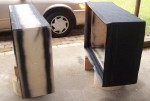
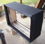
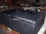
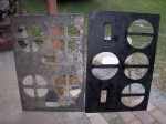
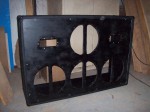
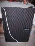
Rather than use paint on the baffles, I decided to use jet black stain mixed with standard rubbing alcohol applied with a paint sprayer. Using this allows the ‘inside’ cabinet view of the baffle to have that ‘aged’ look where you can still see the woodgrain, much like the inside of most vintage JMI baffles. I painted the outside portion of the baffle semi-flat black.

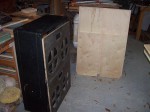
There is a pic of the 7120 / 4120 baffle next to my ‘donor’ Supreme baffle; I did this to show that the cabinets and baffles of these cabinets are slighty larger than AC-100 Deluxe and Supreme baffles.

You will want to do a trial fitting of the baffle to the cabinet in order to drill the baffle mounting holes. Usually it’s 4 or 5 at the top/bottom and 3 at each side. Run your white piping around the outside of the baffle using a few temporary staples to hold it in place. Do your measurements for your mounting holes, as you want these to be pretty even all the way around. When it’s fitted properly, drill your initial mounting holes where you’ve measured the proper spots. This way, when you install the assembled baffle, all of your holes will line up. You will also want to enlarge the mounting holes on the mounting strips on the inside of the cabinet, probably up to ¼” or even a tad larger if need be. This will give you some ‘wiggle’ room when fitting the baffle; these larger holes won’t be seen from the inside of the cabinet, as you’ll use small ‘fender’ washers when you bolt everything down.

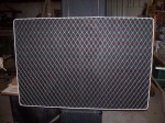
I used VOX ‘scrim’ material glued over the front of the baffle with water thinned titebond. This dries clear and works great. You cut this scrim right to the edge and doesn’t need to be folded over to the rear. Make sure it’s tight over the front and secure with staples as needed. Remove these after the glue dries, usually overnight is best.

After the scrim is on, then move on to fitting the grillcloth. I used 1960’s vintage USA ‘Thomas Organ’ vintage NOS grillcloth, as I had a small supply of this that I had saved that had been cut from a roll that I owned & sold many years ago. I had just enough to do both baffles. You will have to lay it out and staple it down to the REAR edges of the baffle with the cloth folded over & around the sides. (more…)

Posted in blog

Triumph Electronics, builders of the 4 and 7 series for Vox – Part 1

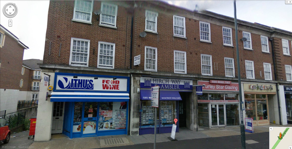
Triumph Electronics – 118 and 122 Brighton Road, Purley – was, from the early 1960s, the company that did much of the designing and a certain amount of the production of various models of amps for Vox. Geoff Johnson was its founder and manager.

triumph_02triumph_03

On the left, 122 and 118 Brighton Road as they are today. The sliproad at left leads to a storage area. On the right, “Fitness First” – what used to be the entrance to the Orchid Ballroom, famous for jazz dance evenings, and later owned by Larry Page, manager of the Troggs. Now and again, amps were tried out in the ballroom.

Quite how Dick Denney found Triumph and Geoff Johnson is unrecorded, but it may be that names were known through mutual acquaintances and trade fairs. Johnson must have a fairly high profile in the late 50s. Trained in the Admiralty Signal and Radar Division during the war, he joined the Department of Electro-physiology (neurosurgery) at Hurstwood Hospital in 1948, remaining there until 1954, whereupon he joined Faraday Electronic Instruments in London. At some point around 1959, however, he left and set up Triumph in Purley, at first manufacturing and importing electronic instruments (medical and domestic). Johnson’s credentials were therefore impeccable.
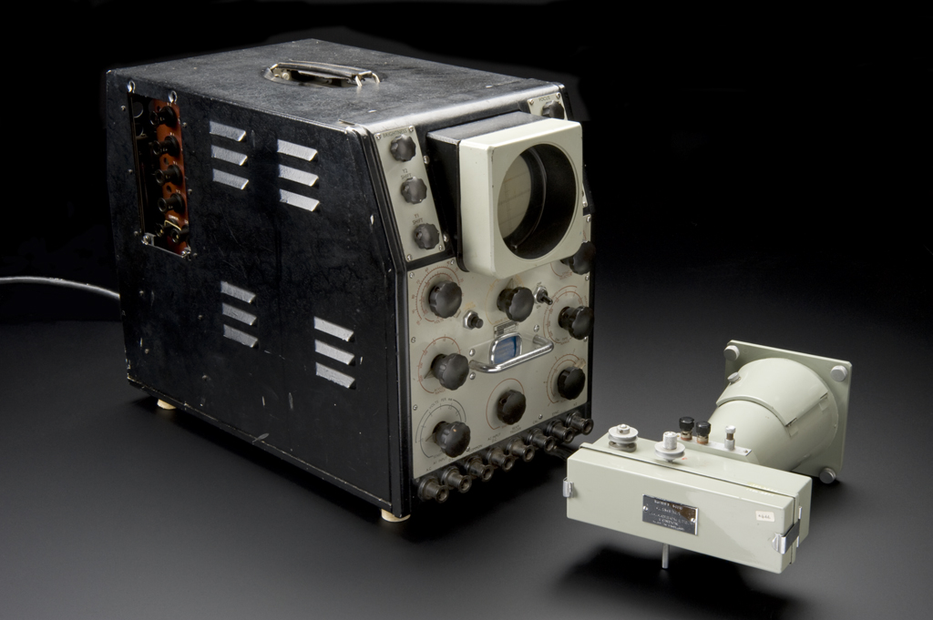
triumph_01

Above, an Oscillograph, developed and used at Hurstwood Hospital.

TRIUMPH, it should be said, also built AC50s, AC100s and reverb units for Vox.  By the time the 7-series came into being, though, production of AC50s had passed to Erith; and only a very few AC100s were asked for by Vox from Triumph in 66. But Triumph still produced Vox PA amps, and amps also for other makers. Work in other fields – devices for hospitals – continued too; and  Les Avery, Triumph’s chief electronic designer, built himself a colour television from scratch (see below).

A small team worked in conjunction with Denney and others at Vox on the 7-series: Simon and Graham are remembered by Carl Nielsen.

Dave Roffey, who worked at Triumph in the late 1960s, designing among other things the Vamp range of amps, recounts:

“As far as I remember, units he had started from the end of the building structure next to the ramp down to an underground car park. I used to take amps down there to blast out. Also in the Orchid when it was convenient. Two shops side by side from the end when I was there. The first, or end shop, ground floor was Geoff Johnson’s office, a room I used for designing amps and a third room with a drawing board etc in for layouts, pcb and chassis drawings, reference books etc. Stairs down to the basement led into the production and test area. Benches for about 8, bending press and guillotine. This might have been spread into next doors basement, but it wasn’t a very large area.”

“Out the back was a common path way behind the buildings. Triumph rented space underneath the Orchid for stock etc access via this walkway. The shop area next door (no. 118) was mainly a stock room for components. A Mrs Andrews, a French lady, was fiercely in charge I remember. Les Avery, the designer of the transistor gear had an office in there, and there also was ECG machine equipment somehow involved with it all. Les designed a colour television, had strong links with RCA and semiconductors, finally going over to them, which is where I came in. I put the first distortion “bite” controls in valve pre amps, which was a hell of struggle considering it was a big no no for the “clean are us” brigade. And a proper middle control! There were some chassis made at Triumph, but quantities came from South Croydon, as did circuit boards when they started to be used. I did a design for the AC30 pcb at one stage I remember.”

(more…)

Posted in blog, Uncategorized

Triumph Electronics, builders of the 4 and 7 series for Vox – Part 2

Building the 7 series

As far as is known, the better part of the design work behind the 7-series was done at the VOX AND BURNDEPT WORKS ON WEST STREET IN ERITH (click on the link for pics in a new window). This was the prototyping stage – formulating the circuit and making the various elements operate and sound as desired. Little is known of this side of things, but it may be that an American Super Beatle amp, which Denney had seen in Sepulveda in late 1965, was looked to for some of the preamp circuitry – at least as a general inspiration.

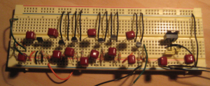
The design process is likely to have been similar to that adopted by Les Avery for slightly later lines of Vox amps. He recalls working on the “breadboards” (perforated layout boards) with Dick Denney, subbing in components by means of flying leads, and testing at each stage, until the desired effect or sound had been achieved.
Breadboard

Once the general design had been outlined, Triumph’s task was twofold: to set up the supply line for production (no small matter to make sure all the necessary components were delivered in sufficient quantities); then to produce the amps. It is worth saying that the resistors and capacitors etc. sourced by Triumph are distinctive (e.g. green bodied resistors, blue Philips caps): they are not found in Vox amps built in the works at Erith, ie. Burndept Electronics, a contractor, and in the Vox Factory at West Road. And these Triumph-only parts, it should be said, are also to be found in the AC50s and AC100s, as well as in the Vox PA amps, that Triumph built, but not in those built in Kent.

Basic production outline

WOODEN BOXES. Henry Glass and Co. (later constituted as “GlaRev”) made the wooden boxes, finished them – providing the tolex covering, corner protectors and vents – and sent them to Purley where they were stored (briefly) until needed. There were two basic sizes – one for the 430, 715 and 730; and another for the 460, 760, 4120 and 7120. Early boxes had removable back panels – three are known to survive – two 7120 boxes, and one 730.

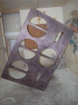
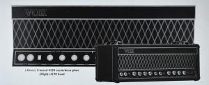
CHASSIS AND PANELS.  Metal was cut to order and treated by a company behind Potter’s Music Shop in Croydon.  Chassis were formed up at Triumph, which had a metal press for the express purpose. When finished they were sent off to Brooklands Plating Co. in Croydon for the panels (made by Brooklands) to be fitted. Panels were attached to the chassis, and openings for potentiometers and so on drilled through both. A surviving unused panel owned by Carl Nielsen has solid metal where the holes for the front controls should be. Illustrated in J. Elyea, Vox Amplifiers, p. 461. *FOR MORE ON PANELS SEE THIS POST.
panel
Chassis were stacked and used in no particular order, ie. an “early” one can easily occur in “late” amp. The same is true of panels. Early ones appear in amps built in late 1966.

TRANSFORMERS. Some of these seem to have been sourced from the Douglas Transformer Co., which is now in Louth, Lincolnshire – click here for its site. The transformers were evidently a particularly important “design centre”. It can hardly be an accident that 4120 and 7120-sized units (and the accompanying choke) fit on a 730 chassis – in other words in the amps that the Beatles received.

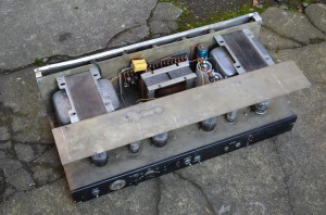
4120_nick_06

Above, top view of a 4120 chassis

ELECTRONIC ASSEMBLY. All 4-series and 7-series amps (including the ones issued to the Beatles) were assembled in the basement rooms (more…)

Posted in Uncategorized

The Beatles – prototypes – Construction / Styling

Prototypes – The Beatles


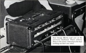
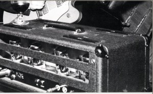
It seems that the earliest working prototypes seen were the ones actually issued to the Beatles,  the first of which arrived sometime around the start of the recording sessions for Revolver, around April 1966.  These UL-7120, 120-watt heads were smaller than production 7/4series 120-watters,  looking very much like size of the smaller 730 size heads.  They were  actually just a fraction smaller than the 730 though , slightly less wide/tall/deep, being  22.5″ by 8.25″ x 11.25″  (the 730 being 23″ x 9″ x 11.5″).

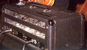
7120_66_2There were other differences too; from the rear,  photos show that the valves were mounted on slightly angled bases, and the rear section could be removed for access to these valves.  This only featured on the early prototypes; it was probably hoped that this would help to ventilate some of the heat from the cramped space of the smaller cabinets.

7120_66_1


The Beatles amps lacked the ventilation space of the “large box”  production sized cabinets; in fact it’s hard to see how they even fitted the transformers in, if they were the regular upright configuration (see HERE for comparison with 730 size chassis).   Maybe this is why the Beatles amps uniquely had doubled up rows of vents on the top; in the colour pic, you can see VOX’s attention to styling/detail in the way the inner vents were a slightly lighter shade of grey.   Some of the transformers for the new line were made by Douglas Chapman.  7120rearcolour

beatles_abbey_road_07


The front panels were diferent too, with different placing/styling/accenting of control legends, a smaller VOX logo, and less evenly placed diamond motif.


Paul’s amp had a “BASS” legend upper right front; John and George’s had none.


Posted in blog

The Beatles – prototypes 2 – ‘special amps’

“SPECIAL AMPS”

In the May 1966 issue of The Beatles Book, a small article appeared under the heading SPECIAL AMPS:  “Vox have designed new 150 watt amps specially for the Beatles, which are half as powerful again as their previous ones [AC100s].  The only trouble is that Mal isn’t too happy with the new additions because he can hardly move them.  You can imagine how heavy they are, because as you know, Mal can lift most equipment very easily.”

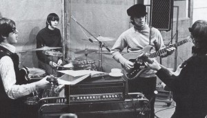
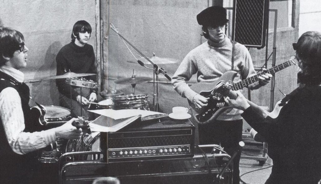
The amps in question were Vox UL7120s which had arrived in April:

Above, the Beatles in Studio 3 at Abbey Road, recording “Revolver”

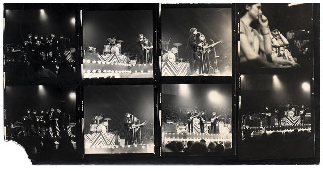
and which were first seen in public at the NME Pollwinner’s Concert, 1st May:
nme_png

Above, contact sheets of shots from the NME Poll Winner’s Concert at Wembley Pool in 1966.  The Rolling Stones’ and Beatles’ performances were not recorded due to contractual difficulties. Below, stills from the fabulous collection of material held by Getty Images.

9113913791139136


Posted in blog | Tagged , , , |

The Beatles’ 7120s – collectanea

Reliable report says that Lennon’s amp, sold at auction in New York in 1998 , conforms to the standard 7120 circuit; only one capacitor and one resistor are positioned differently in relation to the (later) amps examined by our source.

Alan Harding, an engineer at Vox in the 1960s, indicated separately that JMI/Vox did not do things differently for bands, ie. the Beatles received the production model of the time. The early style of box with removable back panel in AH’s view was not specifically a means of aiding valve replacement (at least during live shows).  Concern centred more on whether the speaker cabs would handle the power of the new amps.  The removable back panel presumably followed on from the design of existing boxes (AC50s and AC100s), but was then changed.

In none of the surviving / known photos of the band on stage can a spare amp be seen (though a spare cab was provided at first). Vox/Triumph evidently felt confident about reliability – the amps did contain transistors after all :-).

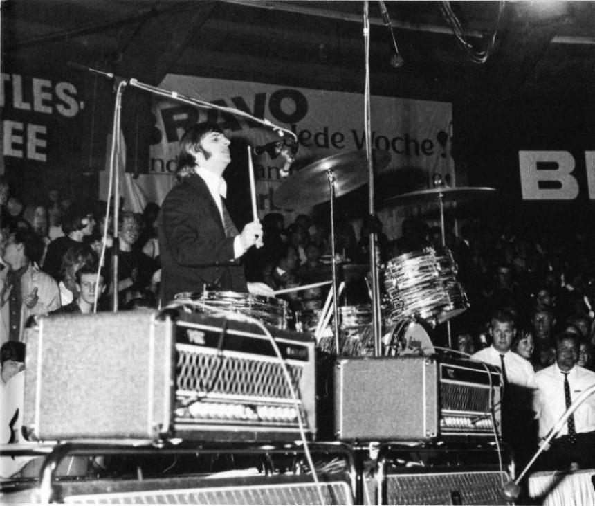
And few problems seem to have arisen – the Beatles used their small box 7120s from May-August 1966, both in the studio and on stage.

Paul’s amp had a BASS logo to distinguish it from John and George’s; and presumably its tone stack was voiced along the lines of a 4120, effectively only one resistor and capacitor value different from a 7120, but a huge difference in terms of the sound obtainable from channel 1. The BASS logo doubtless served to stop Mal Evans putting this amp inadvertently on John or George’s cabs. Otherwise why the logo at all?

beatles_munich_05

Several questions revolve around Paul’s amp though: why did it *apparently* have effects? Does tremolo work with a bass? Could the electronics inside simply have been those of a 4120, but the panel that of a 7120 to match John and George’s?

The intention seems to have been, at some stage, to build small-chassis small-box 7120s in a run, ie. not just for the Beatles. Standard 4120 and 7120 transformers fit perfectly, albeit snugly, on the chassis of a 730 – and as we know, the Beatles amps were, give or take a fraction of an inch here and there, that size (ie. the size of a 730). Hardly an accident.

The power amp schematic for the 4120/7120 (the two amps are identical) is dated 17-3-1966. The preamp schematic for the 7120, as we have it, dates from Nov. 1966, but gives the initial date of release as 25-4-1966, which is close to when the Beatles first received their amps. Unfortunately the schematic omits some intermediary changes in the circuit (which can be seen in surviving amps).

The preamp schematic for the 4120 is dated 20-4-1966


TWO VERY GOOD REASONS NOT TO BUILD A RUN OF 7120s ON SMALL CHASSIS

1) The cost and labour involved in forming sloping cutaways on the chassis for the valves.

7120rearcolour

2) The huge fiddle of fitting components in the exceedingly tight space in the well of the upper chassis.

Posted in blog

Cabs for the Beatles’ 7120s

FOUR CABS

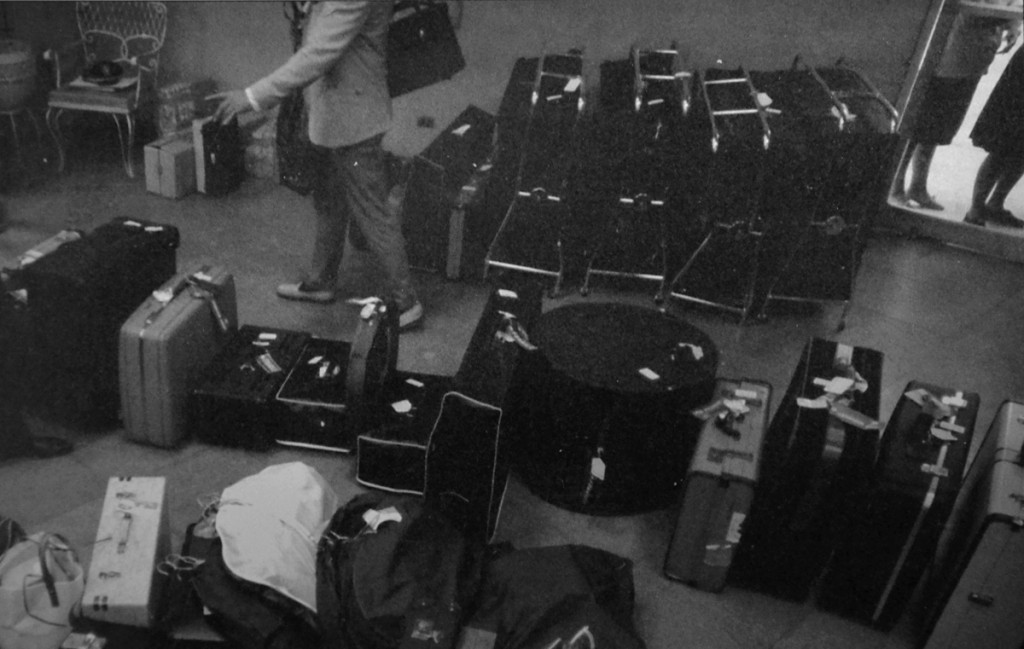
Below, a detail from the famous picture of the Beatles’ gear at Hong Kong airport, a transit stopping off point on the way to Manila, the final concert of the Far East jaunt of the summer 1966 tour. In the background, to the right, are four cabs with trolleys. These are 4/7 series cabs. A couple of the trolleys have their top sections detached, which accounts for the difference in heights.

hong_kong_01

The second cab from the right seems to have lost a wheel, the fourth cab was a backup / replacment….

At least one of the cabs was open backed, as can be seen (more…)

Posted in blog