welcome Vox 4series 7series

welcomeblack


“When we finished ”Revolver”, we realised that we had found a new British sound almost by accident.”

  – Paul McCartney, 1966

sitemainicgrab

newtitles

The life & times of the rare Vox 7 & 4 – series amplifiers, 1966-68.

(**Blog Index, & Gallery links now all active).   Further entries added as website unfolds.  Either scroll down ↓  to see just the most recent posts on history / amps / memories (click on  ‘more..‘  to expand full post),  or see blog post INDEX above for the whole list & links to individual posts.


Posted in blog | Tagged , , , , , , |

ul 710 tech update/observations

Update from the excellent researcher ‘Tuomo’, with some more revised observations;


UL710 schematic

The known schematics

There are two known UL710 schematics at the moment. The official JMI schematic OS/112 issue 2 dated at 4 – 10 – 66 and the other called ‘Un-numbered’.

Jim Elyea published the OS/112 in his ’Vox bible’. It indicates a couple of changes to the original first issue that was released at 11 – 3 – 66. Unfortunately, there are still number of errors in the schematic and maybe for that reason someone started to re-draw the schematic taking the actual amp circuit as reference.

The un-numbered version  also has errors, and it seems that it is just a draft which wasn’t ever finalised. This schematic is following the actual built amps more precise though.

These two schematics have different component numbering.  In OS/112 the numbering is based on the drawing itself, starting from upper left corner towards the lower right corner.  The numbering in the other schematic follows more the positioning of the components in the tag board and placing of the tubes in chassis. I am referring to the numbering of OS/112 in this article.

Since the both schematics have mistakes, I decided to reverse engineer the mystery and re-draw the OS/112 schematic based on my own amp SN 1005. While doing that I noticed some additional changes that hasn’t been documented in issue 2.

The changes before issue 2

The Issue 2 states two changes: addition of R36 and Reverb footswitch.

My amp SN 1005 is one of the first ever made, if serial numbering started from 1000 or 1001. It represents the circuit that should have been documented in the first version. It has two other differences than those mentioned in Issue 2: Also R35 is missing and value of capacitor C18 is 10nF.

In later amps C18 was changed to 100nF and they all have those two additional resistors R35 and R36 as shown in Issue 2 schematic. All amps have had a two-button footswitch which controls reverb and vibrato. It means that the missing footswitch was just a drawing error.

I marked the R35 and C18 related changes as ’issue 1,5’.

The other errors in OS/112

As mentioned earlier there are errors in the OS/112 Issue 2 schematic.

Quite many errors are related to A+ voltage circuit. All amps seem to have EZ80 rectifier tube, so I changed that. Next in line is the point where the A+ voltage is taken to the center of the output transformer’s primary winding. It is taken directly from the EZ80, not after R34. Also position of R10 was incorrect, now it is in position as in the actual circuit. It feeds A+ voltage to all preamp ECC triodes, except V1b which gets A+ voltage through R29.

I deleted two cathode capacitors C9 and C15 since they are not installed to any of the amps.

Position of coupling capacitor C11 was also drawn incorrectly. It is connected directly to V2b cathode, not to the other end of R15. Value of R15 is also changed to the one in amps (1k5).

Another mistake was in V3 and V4 cathodes which were not connected to each other as they should. I also changed the value of the cathode resistor R20 to the one in amps (133R / 5W).

Also, the vibrato oscillator circuit is now fixed. The change is related to the position of the footswitch. If you do not own the footswitch, then your vibrato isn’t working, since you need it for shortcutting the oscillator circuit.

The last changes are the loudspeaker switch and 8 ohms winding in T2 that I deleted, because UL710 has only 15 ohms output and switch is missing.

I have listed all corrections that I made to re-drawn ‘issue 3’. I have also drawn another picture that shows the components in the main tag board. I hope that these two pictures give you some help with your amps. I have tried to check everything for avoiding to creat any new errors, but I cannot be 100% sure if everything is correct.

NOTE: I DON’T TAKE ANY RESPONSIBILITY OF THE USAGE OF THE PICTURES, THEY ARE DRAWN ONLY FOR INFORMATION PURPOSES AND THEY CAN STILL HAVE ERRORS. WORKING WITH AMP WHEN CHASSIS IS TAKEN OUT FROM THE CABINET IS DANGEROUS DUE TO HIGH VOLTAGES. LET YOUR ENGINEER DO THE WORK!


Posted in Uncategorized

prototype vox 430

A nice rare prototype 430 has surfaced;

It’s nice to see confirmation of something we deduced before – that the ‘bass’ channel legend for some reason was here left as ‘vibrato’, though there were no vib/trem controls.  Presumably that was part of the evolving prototype design and re-use of stencils.  Note too the appearance again of another detail – a MAINS legend shifted to the right.  We saw this on one of the Beatles tour amps, so  although the 430 is very different from their 120-watt units with vib/trem/reverb,  this tells us a little about the production of their ones too.  It would seem the shifted-legend wasn’t just an accident of production, but maybe part of a re-used stencil or set of stencils, an alternative layout that was dropped.  Hard to tell what’s original – the inputs don’t seem to match – but there seems to be a Bulgin power connector needing extra support again.

Because of the different diamond style, it’s been hard to gauge the exact size of some prototype photos, like the one in the book “The Vox Story”.  A publicity photo there showed a very similar looking prototype in two photos, one in a tall trolley mounted above two cabs;

A 4-series amp, apparently a 460, used to illustrate an amp with a stacked cab trolley. Carl Nielsen recalls seeing the Troggs at the Orchid Ballroom (behind the Triumph building) with a similar set-up, on the revolving stage.  He said he recently met the Troggs guitarist Chris Britton, and was able to tell him himself how great they’d sounded, and asked what happened to the amps.  Chris told him that they’d finished a tour in Germany, and had arrived back, bringing the amps with them.   Exhausted from the tour, they had switched the amps on for a session, but they’d forgotten to change the euro voltage setting on the back, and ….the amps were fried.

From the panel though, we see that the one in the promo stack amp photo was a larger box – it was apparently in fact a 460 prototype.   You can just make out a bit of silver on the right side of the top panel, where it seems originally there was going to be a model number.  On this 430, there’s some worn silver there too – with what now looks to be what’s left of a ‘430’ legend.   Given the wear, it’s possible that things like these individual numbers, and possibly the BASS on Paul’s amp & something undetermined on Bill Wyman’s amp, were added later.

The fact that this is another finished proto amp, like the 4120 used by Bill Wyman on the ’66 USA Rolling Stones tour and others, suggests that the amps in the Vox Story and promo catalogue photos, which included a 7120,  were finished amps (not just empty boxes with demo fronts).  The 4120 and 7120 protos would seem to have already been large-box style, though with the single handles they looked similar to the smaller Beatles-sized prototypes.

Posted in Uncategorized

Newly discovered Beatles proto amp – summary/overview

SUMMARY

Beatles amp on ’66 tour, © Beatles Book Photo Library

Newly found Swiss chassis/amp

Just to summarise where we are with the research so far;


Lower edge of Swiss amp today, placed just above same section of Beatles tour amp in 60s below, photo © Beatles Book Photo Library


  • A NEWLY DISCOVERED AMP CHASSIS from Switzerland has been found to match one used by the Beatles, in Germany, on the 1966 tour (seen in photos above).
  • It matches and helps to explain the different construction of the Beatles proto amps.  Much bigger transformers, cut-out corners, same legends, exact same proto diamond pattern/styling on front (though Paul’s had a BASS legend added on the top front panel).
  • Despite the switches being swapped and the power socket turned and re-attached, The same marks can be seen in many areas.  These include not just scratches/gouges revealing bare metal, but subtler, more complex sub-surface damage and radiating cracks to the enamel, that become more visible with certain angles/lighting.
  • One lower transformer bolt in particular on the new Swiss amp was re-drilled, markedly higher and to the left, while the top bolt above used the pre-drilled hole.   This is matched by the Beatles amp.
  • The newly-discovered chassis was drilled in production with a larger hole for a different power socket, but then fitted with an Amphenol socket, which barely had enough metal to securely fasten a bolt.   This weak and compromised setup broke with some knock, and the connector had to be turned from its normal upright position with the connector and red circle on top, to try to fasten it again.  This problem, leading to a power connector oddly-turned round from normal upright position,  can also be seen on a second amp used by the Beatles on the same tour.  It seems the chassis on at least two amps was drilled the same way, with a bigger hole, leading to some failure of the connection.  This then led to the power socket having to be turned to try to make a more secure connection.
  • Here are some of some of the most obvious corresponding matched details;
  • Only one of the lower bolts visible over lower bar of removable back section; lower bolt is raised and moved left, bolt above in normal pre-drilled hole.   © Beatles Book Photo Library

compare with;

Only the top left bolt uses pre-drilled hole; the others have had to be re-drilled. Lower left bolt isn’t just shifted left, but also shifted higher.  Same anomaly, same bolt, shifted in exactly the same way, higher & left, as on the Beatles amp.


Beatles amp (Black & White) top, © Beatles Book Photo Library.  Modern-day Swiss amp below. Complex of marks under Amphenol, particularly downward line and ‘V’ shape


Scroll down for full comparison/details in the previous posts, or follow these links;


Swiss amp = Beatles amp; photo comparisons  part 1

Swiss amp = Beatles amp; photo comparisons  part 2

early chassis found -investigation   part 1

early chassis found   part 2

early chassis found  part 3 

early chassis found  part 4


Posted in Uncategorized

SWISS AMP = BEATLES AMP : PHOTOS 2

SWISS AMP = BEATLES AMP : PHOTOS 2

The view of the inside rear metal section behind the valves is partially obscured by the amp’s removable back section.

Only one of the lower bolts visible over lower bar of removable back section.   © Beatles Book Photo Library

You can clearly see three of the bolts right along the top edge; what you can’t see is three corresponding bolts directly underneath, along the bottom.  A little bit of one was just visible though (indicated by bottom arrow).   For some reason, this bolt was higher than the others.  The valves are slanted, so they aren’t a good guide for straightness, and the small valve there is tilted slightly to the right too.  By comparing with the four bias-control switches though (four black adjusters mounted on back panel, in middle of image), you can see that this bolt isn’t just mounted slightly high; it’s shifted for some reason to the left too.

The first pictures of the Swiss amp showed the back, with all the valves.  When we started looking into the amp, we requested another one, of the Amphenol connections from the back.  This lower bolt wasn’t visible on any of those pics.

We now asked for some new photos – with different angles and lighting – to see if it brought out some of the marks (it did).  We also asked (without pointing out why)  for a photo with that specific small valve removed.  This would reveal the hidden bolt, and we asked for one showing both the top and bottom bolt, so we could judge if it was moved over to the left.  If it turned out to be either exactly below it, or at the same level, then the top part of the chassis would be different.

Among the photos we received back, there was this one with the valve removed to show the hidden bolt;

This explained why that one bolt was partially visible in the black & white 1966 concert photo.  For some reason only one of the pre-drilled holes was used to bolt the transformer; new ones had been drilled slightly back, though they had succeeded in forcing one at the top through*.  Maybe after a struggle with that one, new holes were drilled for the other three, leaving the inside bottom bolt moved over to the left.  The hole (hard to access to drill there) was slightly higher too.  The bolts on Paul’s amp are visible in another photo, and you can see that they put the transformer in on that one with no need for re-drilling.  We don’t have clear photos of the bolts on the other non-bass amp, but we can see this re-drilling wasn’t standard.

The fact that it’s out-of-position on this amp, in exactly the same way the 1966 photo, isn’t definitive, but it is yet another point to add to all the other points of correspondence.  The angle of the slot in the head of the lower bolt, and the one above it, look to be pretty much in the same position too.  So does the one on the far left, though the corresponding one to that seems to have turned, loosened/tightened at some point.

Moving back to the voltage-selector area, there is another distinctive anomaly.

Beatles tour amp above, © Beatles Book Photo Library. Swiss amp below

There are numerous corresponding marks here, one of the most obvious ones ringed on the left (with a similar one below it). The anomaly we want to look at though is arrowed, just above the 225 legend around the voltage selector.  You can see in the clearer modern Swiss photo below that there was a little nick/production anomaly, a dot just above the central 2 of 225,  which matches the anomaly seen on the 1966 photo above it. (The first ‘2’ seems lower also, or the middle one slightly raised).  The resolution isn’t perfect, but the screw on the right seems to be in the same position, the left just fractionally loosened/tightened.  Note too the fuse legends –  the positions on the Swiss amp are reversed in the same way as the 1966 photo, with the 2 Amp fuse on top.


(* Carl Nielsen described the huge difficulty he had replacing one of these huge transformers, saying it just wouldn’t go down onto the chassis.  He spent almost a whole day getting the old blown transformer out, and trying to force the new one down onto the chassis.  When we asked him about these new transformers, he recognised them instantly as being the ‘bloody heavy’ones he’d worked on, which meant the amp had needed two people to comfortably get onto the bench.  He said it wasn’t his wiring though, which he remembered – so this wasn’t the amp he worked on).

Posted in Uncategorized

Swiss amp = Beatles amp : photos 1

Swiss amp = Beatles amp : photos 1

To kick things off, here are some photos of the left side of the panel, with some of the more obvious points circled.

Beatles amp (Black & White) top, © Beatles Book Photo Library.  Modern-day Swiss amp below. Complex of marks under Amphenol, particularly downward line and ‘V’ shape

Some of these marks are caused by hard scratches/knocks which chip away the enamel to reveal the bare underlying metal.  Some shapes are less visible in some head-on photos, but heightened by certain angles/lighting.  This suggests radiating impact damage/fracture of the enamel, just under the surface.

Compare line going up from right of  another V-shaped mark/chip by top left of Amphenol,  in two photos of Swiss amp (Beatles 1966 amp in black & white in centre,© Beatles Book Photo Library).  It isn’t so clear in top photo, but underlying damage comes out more with different angle/light

Moving towards the middle of the rear panel, we have the Standby switch.

1966 b/w amp left © Beatles Book Photo Library, Swiss amp right.

Here are the marks under the Standby switch.  Note how some blow has scratched, possibly taking a chip out of the top left of the  ‘O’ of  the ‘ON’ legend.   We’re at the extremes of even this highly detailed image, but there’s a slight suggestion in the 1966 photo of similar damage, probably from whatever caused the scratch.  The switches  today have been changed over to metal; we suspect that this was done in-house by Triumph.  Maybe after damage during the tour, it was returned or recalled for a make-over back in Croydon, rather as Carl Nielsen recalled switching a blown transformer on one of the Beatles models that been similarly returned to Triumph.

On the right side of the rear panel, we have the marks under the footswitch.   Though screws and bolts seem to have been tightened here and there over the years, several remain in the same position.  Here the footswitch screws in the corner look to be the same, but the ones on the ohm selector look to have shifted.  The may have been tightened when it was given an overhaul,  or loosened in all the travel by train/plane/car on tour.

Beatles amp above, © Beatles Book Photo Library

On the Footswitch legend itself, you can see what looks like a flaw/blemish dot just beyond the top right of the W.  Again the image is too blurry to say for sure what’s there,  but there does seem to be something reflecting beyond the top right of the W in the 1966 Beatles panel too.  (Although the F is slightly high on both, this seems to have just been from the stencil used.  It turned up on another amp with prototype features, so we don’t think the high F is any kind of distinguishing mark.  That’s not the case though with this dot shown here, beyond the last upstroke of the ‘W’).

Swiss amp above.  Beatles tour amp below, © Beatles Book Photo Library

More photos & comparisons to follow…..

Posted in Uncategorized

early prototype chassis – Beatles connections – part 4


As we brought the Swiss amp closer to the production of the Beatles models, it brought back previous discussions and ideas.  One of these was a feeling that the accepted history of the Beatles amps – that they were given three prototype amps, which they used in studio and on tour – might be wrong.  There was no conclusive evidence, just a feeling of doubt from looking at blurry photos from different angles – but a suspicion or gut-feeling remained that they might have had a fourth amp at least.

There was another thing we couldn’t resolve too.  We couldn’t tell with the photos we had, but we started to get the sense that one of the Beatles amps might also have had a skewed/re-drilled Amphenol power connector.

Germany tour, 1966.  Note also how on this amp, the “MAINS” legend, usually above the power switch on far left, is here shifted to the right. This leaves it between the switch and the Amphenol power socket, unlike the others


If this was true, it would be possible that the Beatles ones might have had Amphenols thinly attached over a Bulgin hole too,  just like this Swiss one.   We just couldn’t say for sure though – it could be the reflection of lights playing tricks, or the angle.

To try to work these problems out, we reached out to the team at Adams Media. We wanted to see if there was any chance of getting a closer view of a section from a photo of the Beatles 1966 tour in Germany, which showed the back of an amp.   When we got a response later, we were blown away by the  help they offered us.   They’d gone to quite extraordinary lengths to help, crafting beautiful images for us direct from the originals, at high resolution.  They showed blow-ups of the panel section in astonishing detail –  especially one photo with Mal looming over an amp as he put equipment on the stage.   They would totally change our thinking… and lead to an amazing discovery.


Right away, one photo clearly showed us that the amp with the shifted-mains-legend with George did indeed have a turned Amphenol connector.  This raised all sorts of questions – and put paid to any lingering doubt that the Swiss amp was just some kind of mis-drilled experiment.

The fine detail of the photos raised other questions too – like the nagging doubt over the question of whether there might have been a ‘fourth amp’. Armed with the new photos,  we started to look into this again (we’ll have to come back to the complex issue of the question of a fourth amp & the twisted Amphenol later).  This is the background to how we came to be looking, in some detail, at the exact placement of the labels/legends on two back panels.

We were comparing them to try to work out if stencils or templates had been used.  For a more detailed comparison, we pulled up a modern photo of the Swiss amp, and compared that with a Beatles amp from a 1966 concert in Germany.  The switches were different obviously on the Swiss amp, but the position of all the legends – not just around the voltage selector – seemed to match up.  In fact, the legends seemed to match exactly; the two panels even had similar scratches and marks around the power socket.   To compare the legends, we’d put one image directly above the other for a more direct comparison.  Put this close together, the similarity of one thing in particular was suddenly quite eye-catching.  The two panels had different marks obviously;  some scratch / knock marks around the connector though were astonishingly similar.  One ‘V’ shaped one in particular really leapt out, near a line scratched downwards under the Amphenol connector;

Not exactly the same dimensions (smaller image above of Beatles amp) but enough to show similarity of  ‘V’ shaped mark, relative to other marks in the same area, beneath power connector. Swiss amp below; top image is enlarged detail of Beatles tour amp ( © Beatles Book Photo Library)

Looking at other marks, you could see there were still differences – one had decades more wear and tear obviously.  Gradually though, under the newer markings,  more marks matched up with the ones on the panel in 1966.  At first we’d been looking at two different amps; as more and more marks matched up though, with a sense of disbelief, the two amps started to merge.  It started to look like two photos of the same amp, with the original marks on one of them being overlaid by some new scratches and marks from more than 50 intervening years.


We’d started by looking into the possibility of a ‘fourth’ Beatles amp.  Now, that path had led us instead to something completely unexpected.  It looked like another Beatles amp had been staring us in the face the whole time.

original © Beatles Book Photo Library


The detailed photos we’ll be using for comparisons were sourced direct from the original of this photo.

Taken at the Krone-Bau, Munich on June 24th 1966, it shows Mal Evans placing guitars on the right hand corner of the stage, where George’s amp was normally placed.  In the following posts we’ll go through details of the Swiss amp, side by side with the amp here – to show why we are now certain that they show the same amp.

To be continued


Posted in Uncategorized

early prototype chassis found; Beatles connections part 3

TRANSFORMATION


Having following some leads which seemed to be dead-ends, we’d now stumbled on something that was shedding real light on these first Beatles amps.  We still couldn’t tell how the Swiss amp fitted into the picture, but it was no longer some dead-end one-off.  It seemed to be more and more closely connected, although there were questions still about which power connector it had originally been built with.

We tried using some more side by side comparisons of the legends on the swiss amp and the different Beatles amps.   While comparing pictures side by side the day before, we’d noticed that you could see the same white points in the same places on different photos, on the flat panel behind the valves.  These must be the bolts holding the transformers in place.  Having found more pics all suggestive of rivets on the Beatles amps to secure the cut-outs, we looked again at these indications of the transformer bolts, and found something rather unusual.

Details of two different 7120s used by John and George on the German tour – left, used by George at Grugahalle Esssen, 25th June 1966; right, probably used by John, Grugahalle Essen, 25th June 1966.


Here you can make out where the bolts are along the top edge, behind the valves;  note too how close the bolts are to the top in the cramped space. (Barely any ventilation; the 7120 was made taller in production to try to help vent some of the heat, but the Beatles models must have been exceptionally hot, with transformers virtually scraping against the wood).

Now look what happens when you add the Swiss amp for comparison.  For starters, there is a cut-out, visible on the Beatles amp on the right.  It is in the top left corner, in the metal screen that folds back over the valves.  As well as that, you can see that the bolts must indicate a super-large transformer, just like the Swiss amp;

Right top bolt, roughly over the smaller valve.  Note too cut-out corner section, top left of amp on right (ringed)

Let’s remind ourselves with a rough comparison of the size of the Swiss transformers and a production model;

The central choke has two sections; the width of one section is roughly equal to width of central section of smaller transformer in normal amp (left).  On Swiss amp (right), the transformers are clearly much larger

The Swiss ones are different – much wider, heavier, and by inference capable of handling more power.  The central core on the power transformer of a standard production 4120/7120 amplifier is about 5.8 cm (2 1/4″);  the same core on this Swiss power transformer is almost 9 cm (3 1/2″).

Power transformer on Swiss amp.  Though measure here starts from edge of shroud, you can see that the central core is 8.8cm wide (3.5 inches)

Let’s see a comparison of the positions/spacing of bolts holding a normal size transformer with the bolts for the bigger Swiss one;

See how a normal-size transformer is tightly bracketed by bolts on both sides, between the big valve and the smaller valve. In the Swiss amp though, the right bolt is over the smaller valve, & the left further off to the edge

This isn’t an exact comparison obviously, but it’s enough to see how you can tell the size of the transformer behind.  The Beatles ones and the Swiss one, seen from behind, have bolts that are hidden, or almost hidden at the bottom right, behind the second small valve.  The Beatles bolts and the Swiss bolts look to be the same distance apart;  the regular transformers though have bolts that frame the kt88 valve.

It was fairly clear now that the Beatles amps had bolts placed differently, just like this Swiss amp, for the same bigger & heavier transformers.  They also seem to have been riveted for a cut-out corner just by the mains switch, as the Swiss amp is.  Now we knew what we were looking for, we could even see cut-outs in the metal cover over the valves.  Our conclusion was that the Swiss chassis was indeed of the same time and style in nearly every respect as the Beatles amps.  The Swiss chassis seemed to be showing us pretty much what the guts of the Beatles amps would have looked like.   We could use it now to compare details we’d only seen in blurry shapes before, to compare things like the placing of legends.   Each discovery was taking us much closer to the actual amplifiers used by the Beatles in 1966.   Just how close, we were about to discover.

To be continued….

Posted in Uncategorized

early prototype chassis found; Beatles connections part 2


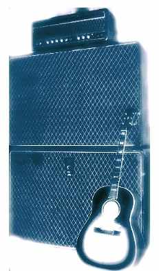
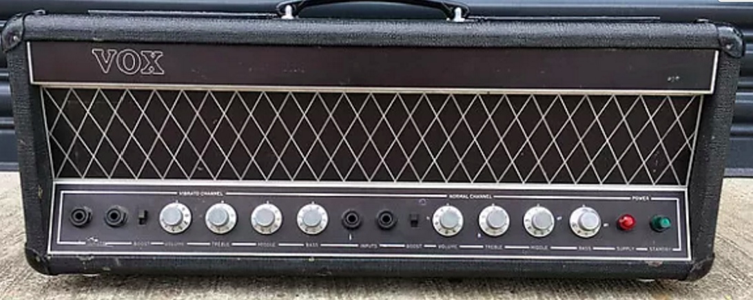
SOME STRIKING DETAILS

We weren’t getting very far looking for the similarities to the Beatles amps, because despite all our efforts, no photos have been released of the inside of the Beatles models.  We can’t see around corners, and we can’t see into the past with x-ray eyes.  We tried looking at the problem from both sides,  asking if there was any evidence for and then against it being of the time the Beatles amps were made.

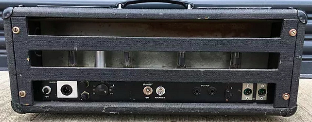
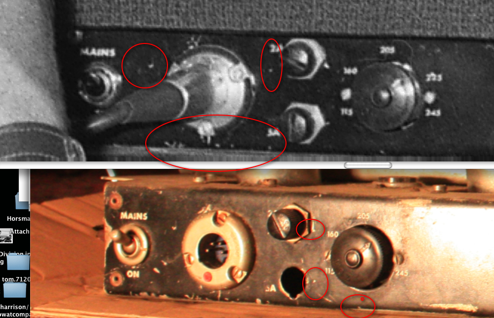
The only thing that really stood out as being visibly different from what we could make out in the photos of the Beatles amps initially available to us was the power connector.  Photos show the Beatles 7120s with a round Amphenol connector, held by 3 bolts.


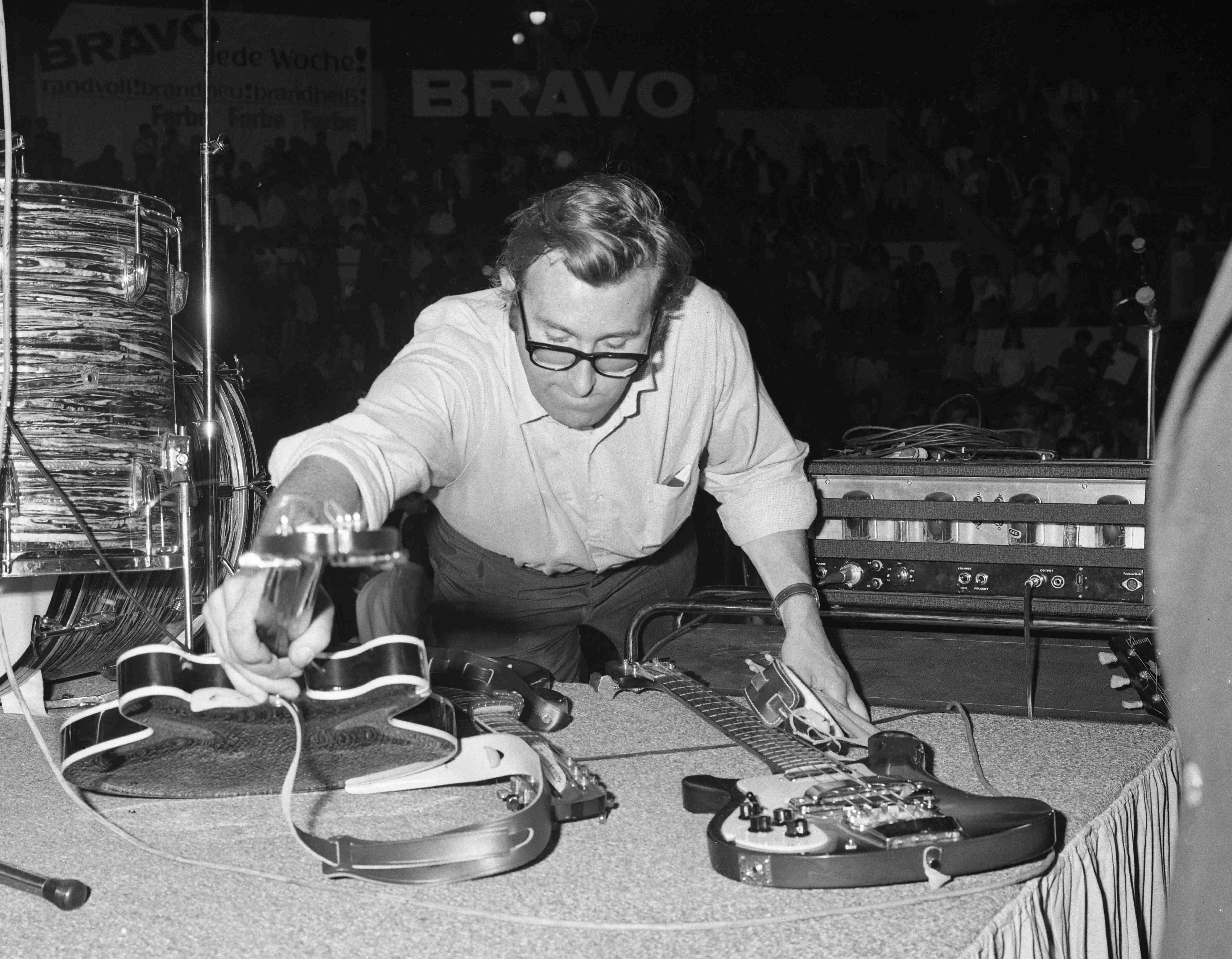
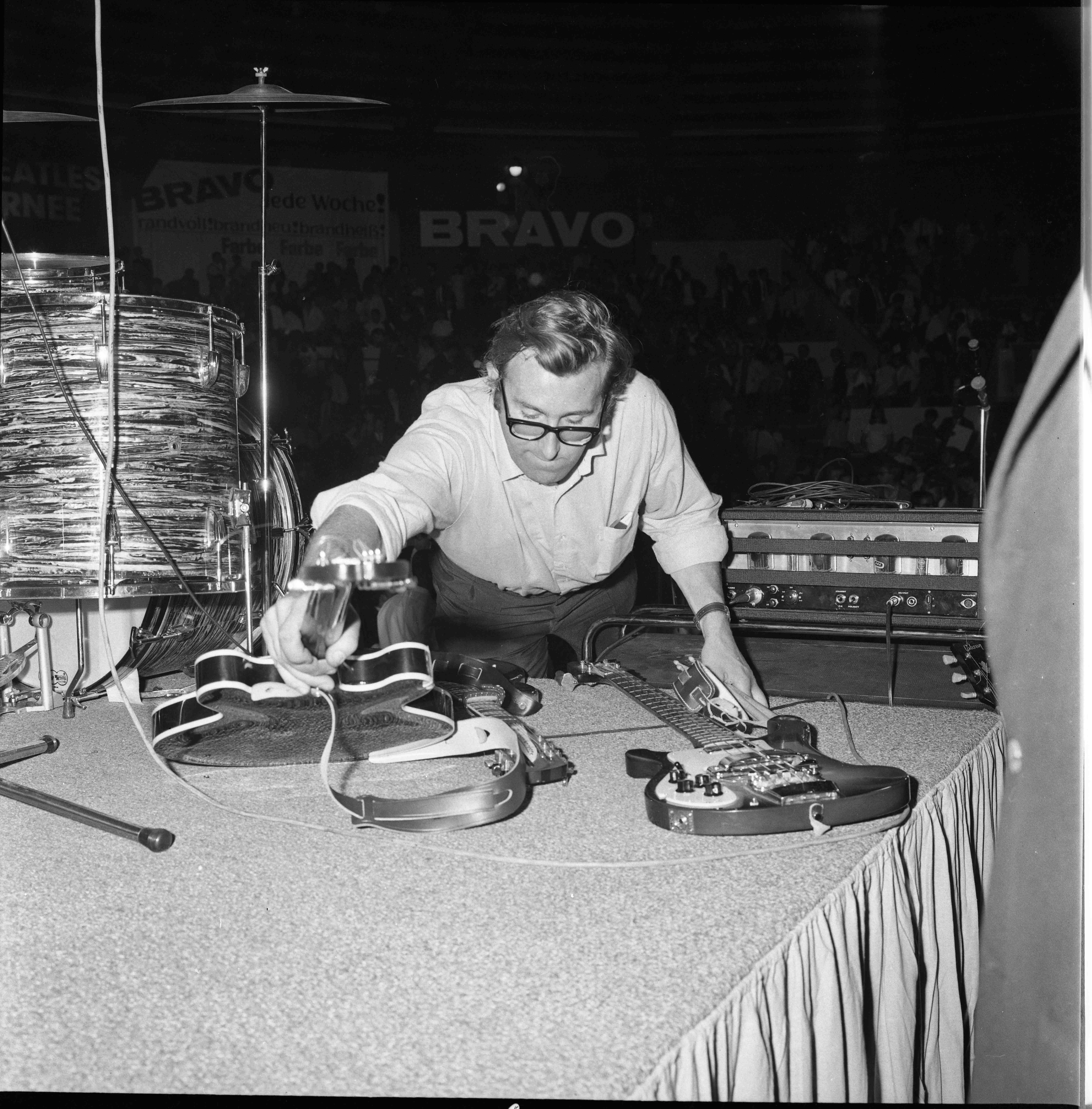
Detail of one of the Beatles’ amps on stage, Munich, 24th June 1966. 

Amphenol power-connector, lower left, with red mark on top

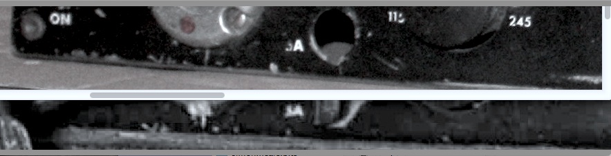
This Swiss amp had the same thing; but we could see something was different though. On the Swiss amp, the socket was mounted upside down (red dot at bottom).

The Swiss amp’s Amphenol power socket.

The owner of the Swiss amp understood how difficult it would be, given the lack of details of the Beatles models, to tie it to any particular part of the development timeline.  He was very helpful though providing what information he could, and sent some photos, including one showing the power plug from the back.

Note that the provision of red dots on power sockets was something that Amphenol only did for Vox – an order that presumably went through the Amphenol factory at Whitstable, a short way down the Kent coast from Dartford.

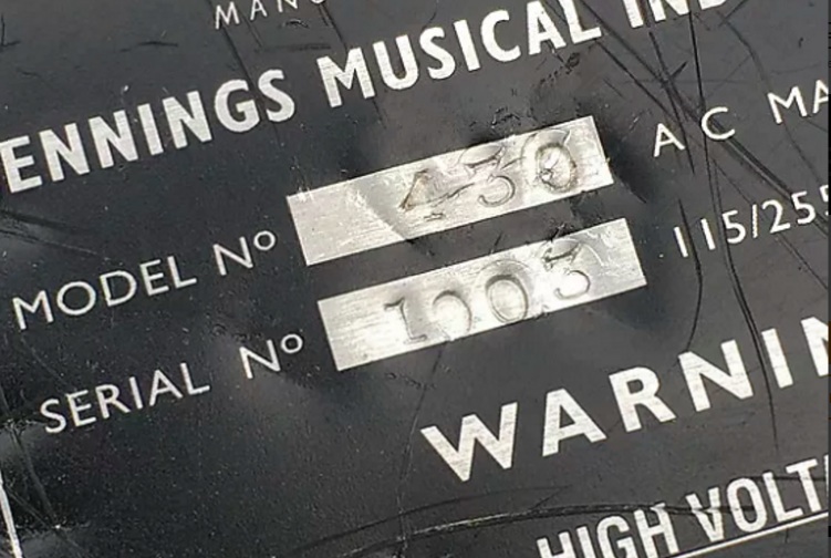
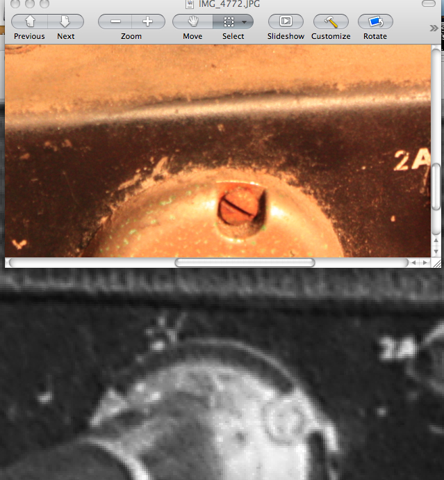
Currently of course the socket is upside down; and the factory-made hole in the chassis – ie. factory-made at Triumph – is for a larger Bulgin bakelite fitting.

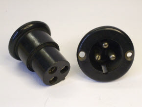
Above, a standard British Bulgin chassis socket and connector.

When one looks at the back of the Swiss amp’s socket in detail, however, it becomes clear that the Amphenol was originally fixed in the hole the correct way up initially and later remounted (turned by around 170 degrees) when its fixings loosened. New fixing holes were made to secure it. Remember, this is an Amphenol specially made for Vox (with a red dot).

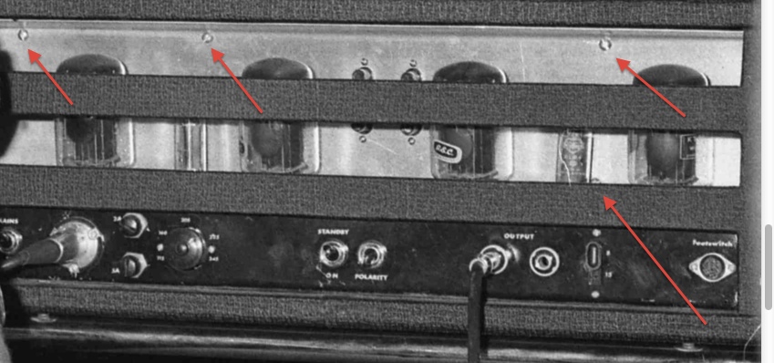
Above, a schema showing the original arrangement, fixing holes for the Bulgin unused either side, and the Amphenol fixed initially at points 1, 2 and 3.

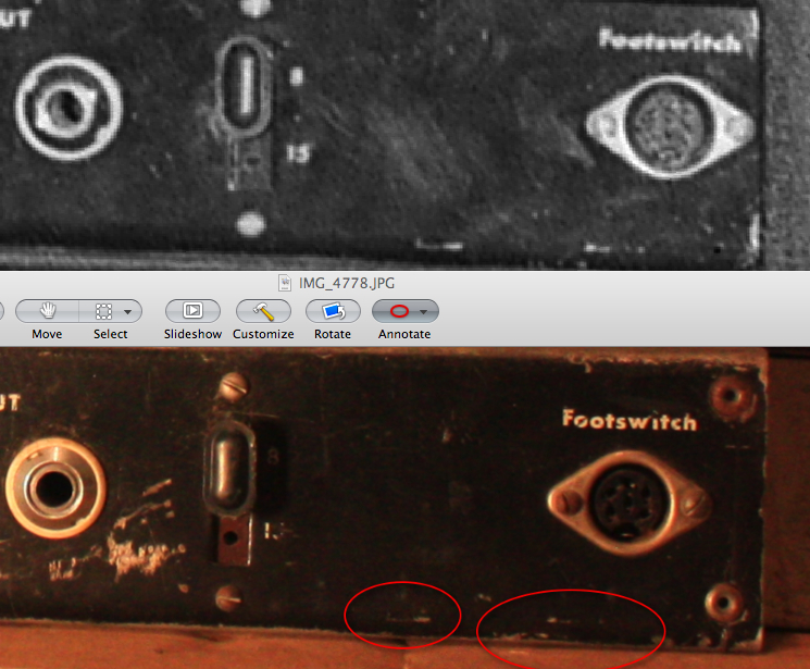
Below, a detail of an early large chassis 7120 (early style front panel, box with removable back panel) to show a Bulgin power connector in place.  The legends on its back panel are similar to those on the amps issued to The Beatles.  Interestingly, this amp also has the  ‘Footswitch’ legend with a capital F and then lower case letters, just like this Swiss one.  Apart from the back and the outer box though, it looks like a normal sized 7120:

Production-sized 7120, but with proto-style elements. The presumption is a factory-made cut-out for the Bulgin socket, and the socket itself fitted at Triumph. This amp was not made for the Beatles. The Beatles’ amps had their own rationale.

Could amps set up like the Swiss one (with an Amphenol carefully positioned in a Bulgin-sized hole) have been given to the Beatles?   For the time being the question must remain open.  However, it is worth observing that lost Bulgin power leads will have been extremely difficult to replace on the continent.  Bulgins were particularly British.  The making or finding of a new XLR-style power socket will have been a simple job for Mal Evans anywhere in the world.


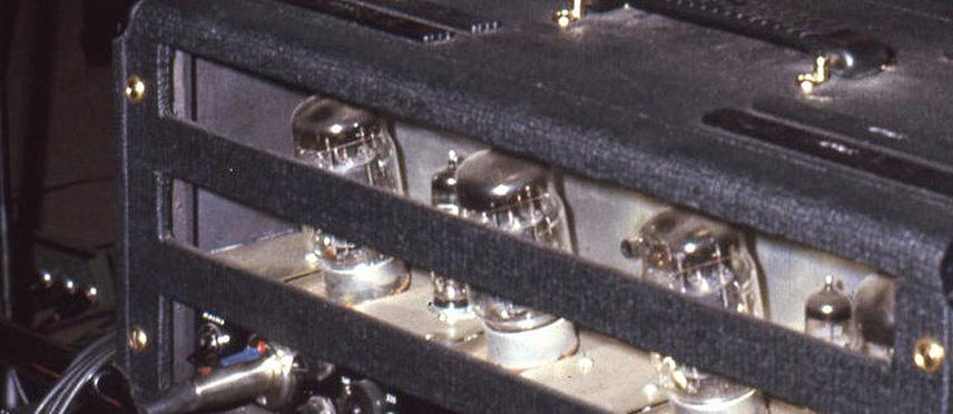
CHASSIS CUT-OUTS AT BACK


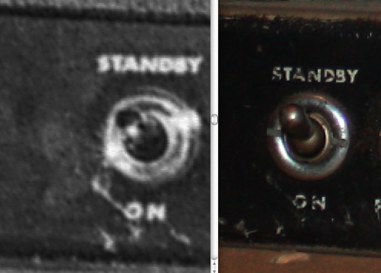
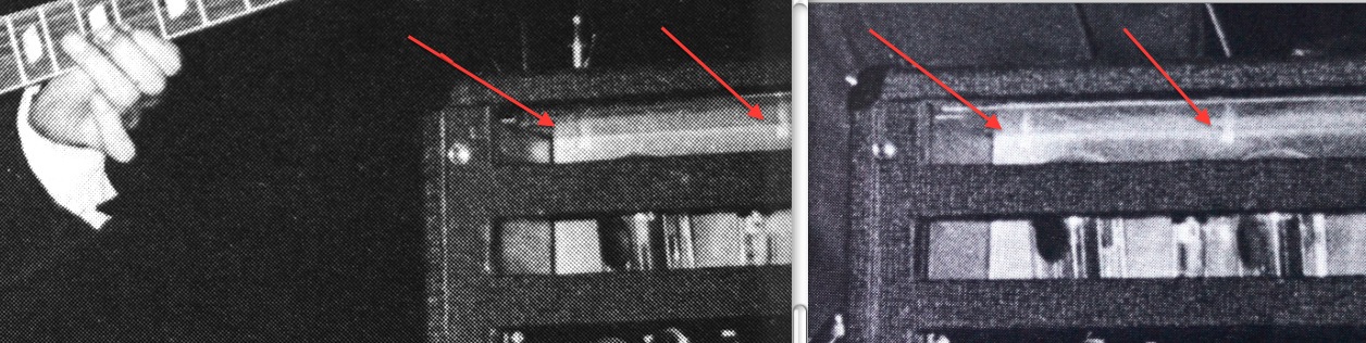
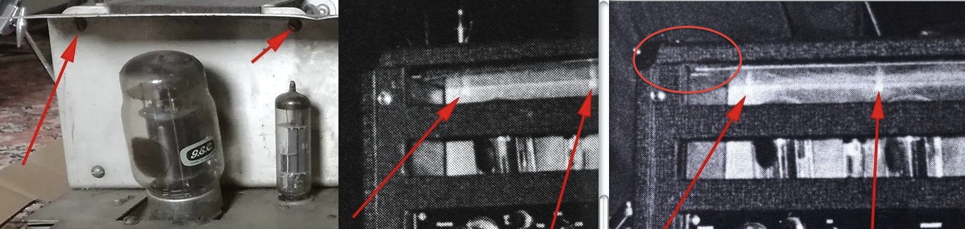
Beyond the power plug, there seemed nothing immediately obvious that would help us to understand the dating and construction, or help us to establish a connection or lack of it to the Beatles amps.  At this point, all we had to go on were details in small low-resolution photos.  As usual, we were left staring at pixellated blow-ups, trying to interpret and compare one pool of dots with another,  hoping to find some suggestion of real details & imperfections.

This was when we noticed that there was a suggestion in some of the Beatles-amp photos of a rivet, in the same place as on the Swiss amp, just above the power switch.  It wasn’t clear, but there was a light patch in the same place on several different photos, enough for us to strongly suspect that this was what we were seeing.

If the rivets were there, then so too were the cut-outs.  It was starting to look as though the Swiss amp was much closer to the Beatles amps than we’d first thought.  So much so that it was helping us to start ‘seeing’ inside the Beatles amps, and start to make some evidence-based deductions about what was going on inside them .  Maybe we could use this mixture of inference and observation to unlock some more of the mysteries of the Beatles amps…..?

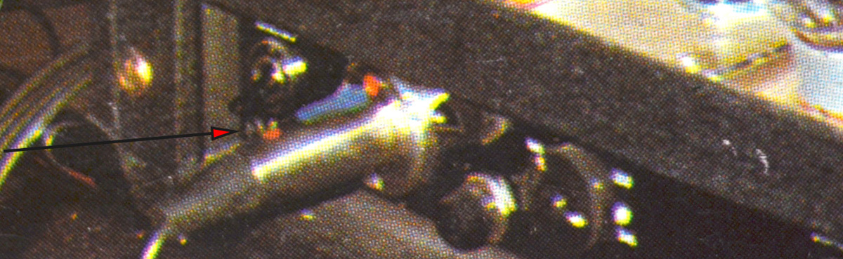
A detail from a photo of Lennon in Studio 2, Abbey Road. The photo is not the one regularly reproduced, but another taken from a slightly different angle.


Part 3 to follow

Posted in Uncategorized

early prototype chassis found; Beatles connections part 1


A fabulous early chassis has been found, in Switzerland of all places, which raises all sorts of questions.  We’ve been trying for years to find out more about the Beatles amps, but it was impossible to get any information on the rumoured survivor.  This example now gives us a real insight into those amps.

Was this the style that the Beatles amps used?  Could it even be an actual Beatles amp?  We know guitars and gear were lent out and ‘went missing’ from various places.  Without any provenance though (this amp was just found in a basement), or any pics of the known surviving beatles amp, all we could do was to examine it as closely as we could, and see where it would take us.

The first thing that leapt out was the odd cut-out corners on the back; we hadn’t seen anything like this before. This didn’t necessarily mean it wasn’t a legit triumph/vox produced amp – but unlike other features, this seemed to be a one-off. These must have been awkward and time-consuming to produce; what was the point of all the time and effort?  The Beatles amps had a removable back panel.  Back in the VoxTalks days, it was presumed that this was so the chassis could be removed from the back for servicing..but the tops of screws were visible holding the panel on.  These obviously went into some kind of support – but these support struts at the back would have blocked the removal of the chassis. The chassis could never have been removed from the back then.  It seems the removable back panel was to make it easier to swap valves, and change the bias. This nice idea was dropped in production though; the single handle was swapped for two, to make it safer and easier to carry, and the whole thing was made wider and taller.  Probably this was for ventilation; they were already heavy units, with their big transformers. The transformers on this Swiss one were even bigger; with little ventilation in the cramped space (the prototypes were smaller, roughly 730-sized), they must have got very hot inside & on top.

It was great to finally see the slanting valve bases in detail; until now we’d only seen limited views of them, obscured by the rear panel. It was presumed before that the slanting bases were to help ventilate the amp; but now, with these ones at least, we can see that the slanting bases seem to be enclosed, so….little help with the ventilation there.  Again, it seems to have been to help with replacement of the tall kt88 valves – the Beatles units were less tall than the production run; they seem to have designed these to allow just enough space to swap out the big kt88s.
One of the most remarkable things though is those transformers; they are (even) bigger than normal.  They are the same height, but much deeper, with shorter ends.  This must have made them even heavier.  Mal was a powerful guy, but seems to have remarked on the weight of them to the driver, Alf Bicknell.  (see  – it-was-almost-50-years-ago-today-moving-the-beatles )   If the Beatles amps had transformers like these, it’s no wonder he complained – he can’t have been looking forward to having to carry these on the planned tours.

The cut-out corners (the overhanging metal cover over the valves has also been cut away) seemed to have been cut to fit around the support struts for holding the rear panel on the back.  There’s a problem though; there are only a handful of clear photos of the amps, especially the back – but one photo with Lennon at Abbey Road does show the lower corner of the rear panel.  The ‘problem’ is that the chassis doesn’t fit around the strut; it seems to just reach it, and then stop. Making and riveting cut-outs like these would seem then to have been a complete waste of time and effort, if the Beatles amps had been the same.  It’s hard to tell what was behind the corner though…  with a bunch of mostly very old photos of the backs of the Beatles amps enclosed in their boxes, it would be very hard to prove if there were any redundant cut-outs in the corner behind.  The same was true of the transformers; there are no photos of just the inner/under chassis.

If there were these redundant cut-outs on the Beatles amps,  the lower strut of the rear panel blocks the view of them.

Back of an early box, with the rear panel removed.  This box is larger & longer of course, so the MAINS switch is easier to get at here (the one in the Lennon pic is right by the edge), and this chassis doesn’t have slanting valves, or cut-out corners.  The cut-out in the new Swiss amp seem to suggest that the rear panel was originally planned to have been flush with the back.  You can see from the Lennon pic that the Beatles ones ended behind the strut anyway, like this one, so the cut-outs would have been redundant.  Note too the Bulgin power socket, sometimes used by Triumph.

It’s hard to discuss the possibility of something you can’t see though, so even though the front of this Swiss amp looks to be from the same template and maybe production run as the ones used on the actual Beatles amps, it was difficult to go much beyond that.  The front had the same characteristics we’ve discussed in other amps with proto fronts; different font for the labels or ‘legends’ making it look faint in photos, different placement of legends, smaller VOX logo, different design of diamonds.  It looks to have the same panel then, and the same slanting valve design, which is itself pretty remarkable.  Without an x-ray of the Beatles amps though or a photo of the insides, it seemed that it would be hard to go much further than that.  Or at least, that’s what we thought, at first.

To be continued…..


Posted in Uncategorized

A further Vox UL430

A Vox UL430 recently on ebay now on Reverb for three times more. No serial number plate on the underside (these were often bumped off), and two red indicator lamps. A couple of small holes appear to have been drilled in the chassis at back.

Posted in blog